Key Takeaways
- Geometric Dimensioning & Tolerancing (GD&T) is a standardized system for defining and communicating engineering tolerances.
- GD&T improves upon traditional tolerancing methods by allowing designers to apply stricter tolerances at critical feature locations while allowing for looser tolerances in less critical areas.
- To effectively implement GD&T, all teams in design and manufacturing need to learn and apply a set of GD&T concepts, terms, and symbols.
In the 1940s, a British naval engineer working in a Scottish weapons factory found traditional tolerancing methods were causing unnecessary waste — some parts were found to be fully functional even after being rejected for failure to meet inspection criteria. To reduce scrap and improve production efficiency, the engineer created an early form of what we now know as Geometric Dimensioning & Tolerancing (GD&T).
Fast forward more than eighty years, and GD&T is an essential part of modern engineering and manufacturing, used across industries such as aerospace, defense, automotive, consumer electronics, medical equipment, and more. GD&T helps manufacturers gain a better understanding of permissible variation, which is especially critical in industries where precision is paramount.
But what is GD&T, exactly? And how does using it improve the design and manufacturing process? This guide will explore GD&T from a beginner’s perspective, explaining everything you need to know to understand its fundamental principles and its role in modern engineering.
What is Geometric Dimensioning and Tolerancing (GD&T)?
GD&T is a standardized system for defining and communicating engineering tolerances. It provides a precise and unambiguous way to specify the form, fit, and function of manufactured parts, ensuring that components meet design intent while maintaining efficiency in production. Essentially, GD&T tells manufacturers just how much — and in what ways — a part can vary while still fitting and functioning properly in the final product.
While traditional dimensioning methods focus on fixed dimensions and tight limits, GD&T allows for a focus on functionality. With GD&T, designers can specify stricter tolerances at critical feature locations while allowing for looser tolerances in less critical areas. This approach ensures that the most important aspects of a part — those that directly impact how it fits and functions in the assembly — are tightly controlled, while other areas can accommodate a bit more variation without impacting overall performance.
Also, traditional dimensioning methods tend to rely heavily on notes and annotations to clarify intended tolerances, which creates opportunities for misinterpretation. A note may be perfectly clear to the designer who wrote it, but other engineers, machinists, or quality inspectors might interpret the specifications differently. GD&T eliminates much of this ambiguity by providing a common set of symbols and rules and a common language with which to communicate complex requirements.
Why is GD&T Important?
GD&T ensures every person involved in the production process has the same understanding of the design intent. This improves collaboration and communication between design teams, manufacturers, and quality control personnel, streamlining the entire process and helping to ensure that parts are made accurately and efficiently.
For example, when a designer specifies that a hole must be located within a certain tolerance zone, they can use GD&T to communicate the exact allowable variation in its position, size, and orientation relative to other features. This specificity ensures that the hole will align correctly with other mating parts, and the common set of symbols used in the notation ensures that everyone who sees the design will understand the precise tolerance requirements.
GD&T also plays a crucial role in reducing production errors and costs. By defining exact tolerances for key features and how they relate to each other, GD&T ensures that parts are made correctly the first time, reducing the need for rework or adjustments.
Additionally, GD&T enables more efficient use of materials and labor by allowing looser tolerances in non-critical areas, reducing waste and improving overall productivity. By focusing on functional requirements, manufacturers can strike a balance between precision and cost-effectiveness, ultimately reducing material costs, shortening production cycles, and passing savings onto customers — all without sacrificing the quality or performance of the final product.
Basic GD&T Concepts Every Engineer Should Know
Learning GD&T is all about understanding how a few basic concepts work together to better control variation in manufacturing. Remember, GD&T is about more than just applying tolerances — it’s about defining the most efficient and effective way to manufacture and assemble parts while allowing for realistic manufacturing variability.
Datums and Datum Reference Frames
The datum reference frame (DRF) is a three-plane conceptual space that serves as the foundation for measuring and controlling part features in GD&T. It’s comparable to the coordinate system used in CAD programs, where every part and feature is referenced relative to a fixed origin. A datum is a reference point, axis, or plane that exists within the DRF and is used as a starting place for measuring.
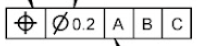
Feature Control Frames
A feature control frame (FCF), sometimes referred to as a GD&T callout, is a rectangular box that defines the tolerance requirements for a specific feature. Feature control frames are what tell manufactures exactly how much variation is acceptable for each feature and in what way. The three parts of the FCF are the geometric tolerance symbol (see below), the tolerance value, and any applicable datums.
Material Condition Modifiers
Finally, material condition modifiers specify how a part’s size affects its tolerance. Practically speaking, material condition modifiers tell manufacturers how much variation a feature can have if the overall part is at either its largest or smallest acceptable size.
Maximum Material Condition (MMC) is a modifier designers use to denote that the geometric tolerance given is only valid when the size dimension is at its upper limit.
Least Material Condition (LMC) is a modifier designers use to denote that the geometric tolerance given is only valid when the size dimension is at its lower limit.
Regardless of Feature Size (RFS) is a modifier designers use to denote that the geometric tolerance given will stay the same no matter the part’s size dimensions.
Key GD&T Symbols and Their Meanings
In addition to the above concepts, GD&T relies on a standardized system of symbols to clearly communicate design requirements. These symbols, used at the beginning of a feature control frame to define the type of geometric control being applied, fall into five categories:
Form Controls
Form controls define the shape of a feature. Form control symbols include:
|
Symbol |
Name |
Summary Description |
|
|
Straightness |
Controls the straightness of a feature in relation to its own perfect form. |
|
|
Flatness |
Controls the flatness of a surface in relation to its own perfect form. |
|
|
Circularity |
Controls the form of a revolved surface in relation to its own perfect form by independent cross sections. |
|
|
Cylindricity |
Like circularity, but applies simultaneously to the entire surface. |


Profile Controls
Profile controls define a feature’s shape relative to an ideal form, allowing for variation within a controlled boundary. Profile controls symbols include:
|
Symbol |
Name |
Summary Description |
|
|
Profile of a Surface |
Controls size and form of a feature. In addition it controls the location and orientation when a datum reference frame is used. |
|
|
Profile of a Line |
Similar to profile of a surface, applies to cross sections of a feature. |


Orientation Controls
Orientation controls ensure that a feature is aligned correctly relative to a datum. Orientation control symbols include:
|
Symbol |
Name |
Summary Description |
|
|
Perpendicularity |
Controls the orientation of a feature which is nominally perpendicular to the primary datum of its datum reference frame. |
|
|
Angularity |
Controls orientation of a feature at a specific angle in relation to the primary datum of its datum reference frame. |
|
|
Parallelism |
Controls orientation of a feature which is nominally parallel to the primary datum of its datum reference frame. |


Location Controls
Location controls define the exact position of a feature relative to other features. Location control symbols include:
|
Symbol |
Name |
Summary Description |
|
|
Position |
Controls the location and orientation of a feature in relation to its datum reference frame. |
|
|
Concentricity |
Controls concentricity of a surface of revolution to a central datum. |
|
|
Symmetry |
Controls the symmetry of two surfaces about a central datum. |


Runout controls
Runout controls ensure uniform rotation of a part to prevent excessive wobbling. Runout control symbols include:
|
Symbol |
Name |
Summary Description |
|
|
Circular Runout |
Controls circularity and coaxiality of each circular segment of a surface independently about a coaxial datum |
|
|
Total Runout |
Controls circularity, straightness, coaxiality, and taper of a cylindrical surface about a coaxial datum. |


By using these symbols instead of lengthy written descriptions, GD&T eliminates ambiguity and streamlines communication during design and manufacturing. In addition to the main control symbols, there are a variety of additional modifiers and symbols used in GD&T to provide further precision and clarity to tolerance instructions. For a full list of symbols and their meanings, check out our GD&T Symbols Reference Guide.
Common Mistakes When Applying GD&T
GD&T is a powerful tool for improving manufacturing precision and efficiency, but there is a learning curve when transitioning from traditional tolerancing systems. Common pitfalls when applying GD&T include:
Overcomplicating Designs with Unnecessary Tolerances
GD&T loses some of its power when engineers apply tight tolerances to non-critical features, which drives up complexity and manufacturing costs. Designers should focus on critical functional features and allow flexibility where possible to achieve maximum efficiency.
Misusing or Misinterpreting GD&T Symbols and Modifiers
Like any skill, mastering GD&T takes time and practice. If designers accidentally use the wrong symbol or modifier, it leads to confusion, miscommunication, manufacturing errors, and costly rework — likewise if a manufacturer misinterprets a symbol or modifier. GD&T training and standardized documentation are key to ensuring that tolerances are applied and interpreted correctly across teams.
Failing to Align GD&T with Functional Design Intent
GD&T is not about increasing precision for its own sake — it’s about enhancing function while balancing manufacturability, cost, and efficiency. If engineers fail to prioritize feasibility, they could end up with overly idealistic designs that are too complex or too expensive to manufacture.
Getting Started with GD&T
GD&T improves on traditional dimensioning methods by establishing a common language with which to communicate design intent clearly and unambiguously. This reduces miscommunication between designers, manufacturers, and inspectors and ensures parts are produced accurately and efficiently the first time.
GD&T also gives engineers a better way to focus on the functional requirements of a part, applying tolerances strategically rather than trying to rigidly control every measurement. This ensures designs are optimized for both performance and manufacturability, keeping production costs in check while maintaining quality.
Sigmetrix has been a leader in the GD&T training and software space for over 25 years. Our solutions help design and manufacturing teams apply GD&T concepts for higher profitability, more time savings, less waste, and faster innovation. Learn more about Sigmetrix GD&T training and software solutions.